
8 Channel 15V/5 A (50 W) Individual Floating Channel Boards
A2519
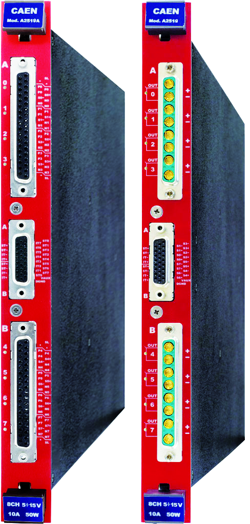
The power supply A2519 is a single width board (5 TE wide) that houses 8 independent Low voltage Individual Floating channels. The A2519 is available in different versions equipped with D-Sub 8-pin or with DB37 connector:
D-Sub 8W8 – 8 pin high current connector
Single width (5 TE wide), 8 channel
(Mod. A2519, 2519C)
DB37 connector
– Single width (5 TE wide),8 channels
(Mod. A2519A, A2519CA)
Consult our connectors reference page for technical information
A2519 Individual Floating channels allow on-detector grounding, reducing the noise level. The floating channels are insulated from each other up to ±500 V. Each output channel is provided with individual remote sensing lines to compensate for the voltage drop over the connection cables.
The output voltage range is 5÷ 15 V, (1 mV steps) with 1 mV monitor resolution (connector and sense voltages). The Maximum channel power is 50 W. The Output Voltage RAMP UP and RAMP DOWN Times may be selected independently for each channel in 1+ 500 V/s range (1 V/s step).
Channels can be connected in parallel with modularity 2 or 4 to obtain higher output power (for 2/4 modularity Iset resolution is 100 mA and Imon resolution is 10 mA). (This feature is not available for A2519C/A2519CA versions.)
Channels feature a PID (proportional integrative-derivative) digital controller, whose parameters (Kp: Proportional gain, Ki: Integral gain, Kd: Derivative gain) are user programmable. In this way, the control loop can be optimized to any load conditions independently for each channel.
Safety features include:
-
Overvoltage detection: if a channel voltage exceeds the programmed Overvoltage threshold value (OVVThr), it is signaled to be in “overvoltage” and is switched off.
-
Undervoltage detection: if a channel voltage decreases below the programmed undervoltage threshold (UNVThr) it is signaled to be in “undervoltage” and is switched off.
-
Overcurrent detection: if a channel tries to draw a current larger than its programmed limit, it is signaled to be in “overcurrent” and is switched off. For A2519C/CA versions the relevant channel can be programmed to turn off after a programmable TRIP time and to provide the maximum allowed current. If TRIP is set to “INFINITE”, the channel behaves like a current generator.
-
Fast Ramp Down Mode (available only for A2519C/CA versions): in this mode the channel output will decrease to 1 V in 100 μs and turn off completely in 1 ms.
-
A global enable/disable connector allows to disable the channels and it is also possible, via front panel logic signals, to enable individually each channel (only for A2519A and A2519CA).
Features
-
8 independently controllable Low Voltage channels
-
5÷15 V output voltage and 5 A maximum current (50 W)
-
Individual Floating Channels
-
DB37 or 8 pin D-Sub connectors
-
Individual remote sense lines
-
Full Digital PID Control Loop
-
Low ripple
-
Under/over-voltage alert, overcurrent and max. voltage protection
-
Interlock logic for unit enable
-
Software Tool for easy channel management
A2519: Manuals

A2519: Download
Application Notes
Brochures / Flyers
Request a Quote

Footer

