
Lorem ipsum dolor sit amet, no vidit nullam reprehendunt sit. Ex vix semper qualisque, te soluta efficiendi qui, corpora prodesset delicatissimi at nec. Sanctus convenire cu cum, pro deleniti platonem no. Est ex quem vulputate, vim accusata intellegam ea, sit an corrumpit deterruisset.
In ludus insolens usu. Ius quidam assentior omittantur id. Eos antiopam postulant ex, postea accusamus est cu. An eam vocibus assueverit, mea affert similique ex. Sit nihil tation ea, vix etiam ludus vocent an.
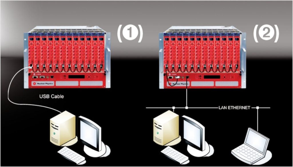
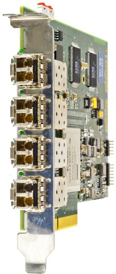
N14xx NIM Power Supply Modules control can take place remotely, via USB or RS485 (1); the latter allows to build a N14xx’ daisy chain network, with the first module connected to the PC USB port and the subsequent ones daisy chained via RS485.
The CAEN NIM8301 Crate allows also to communicate with the first module in the chain also via Ethernet (2). It is therefore possible to build a daisy chain of up to 32 N14xx’s (up to 128 channels).
The SW1470 Control Software (a Java Program supporting Linux and Windows) allows a complete and user friendly management of one or more modules (up to 32 modules = 128 channels).
SW1470 System requirements
- Windows XP/Vista/7 or Linux
- JavaTM Platform, Standard Edition rel.1.5 or newer
- RXTX library for RS232 Java support
- FT232BM driver (if use USB connection)
JavaTM Platform
Go to www.java.com or to Oracle official page to download Java Platform, Standard Edition,for Windows XP/2000/Vista/7, Solaris and Linux.
RXTX Library
Java language does not provide a native support for the serial ports, a third-part library, the RXTX library, must be used for that purpose.
RXTX binary builds are provided as a courtesy of : Mfizz Inc.
for Windows follow this procedure:
Identify your Java Runtime Environment’s folder. For version 7, this usually is c:Program FilesJavajre7
- Copy rxtxParallel.dll to c:Program FilesJavajre7in
- Copy rxtxSerial.dll to c:Program FilesJavajre7in
- Copy RXTXcomm.jar to c:Program FilesJavajre7libext
FT232BM driver
N147X modules are provided with a USB2.0 compliant interface. They can be programmed via PC by connecting the PC USB port with the board USB B-type port; the featured controller, the FT232BM chip requires VCP (Virtual COM Port) drivers freely available here.
The site also provides installation instructions for all Operating Systems
The connection can be performed via Terminal Emulator configured as follows:
- baud rate (the same set on the N147x)
- Data bits: 8
- Parity: none
- stop bit: 1
- Flow control: Xon Xoff
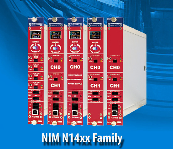
Supported NIM High Voltage Power Supplies Boards
- N1419 – 4 Channel 500 V/200 µA
- N1419A – 2 Channel 500 V/200 µA
- N1419B – 2 Channel 500 V/200 µA
- N1471 – 4 Channel 5.5 kV/300 µA
- N1471A – 2 Channel 5.5 kV/300 µA
- N1471B – 1 Channel 5.5 kV/300 µA
- N1471H – 4 Channel 5.5 kV/20 µA
- N1471HA – 2 Channel 5.5 kV/20 µA
- N1471HB – 1 Channel 5.5 kV/20 µA
- N1470 – 4 Channel 8 kV/3 mA (8 W)
- N1470A – 2 Channel 8 kV/3 mA (8 W)
- N1470B – 1 Channel 8 kV/3 mA (8 W)
Goal of this troubleshooting guide is helping the CAEN Mainframe SYX527 user to quickly identify the most common reason in the system malfunctioning and, if possible, leading him to fix it by himself.
For more information about mainframes see the following web pages:
Problem: The system does not power up.
Possible Issue to check:
- Is the 110V/220V cable connected?
If not: plug it properly. - Is the rear Main Switch on “I” position?
If not: put it on the “I” position. - Is the rear fuse continuity still intact?
If not: replace the fuse. - Is the front panel key on “LOC” (if you are working locally) or “REM” (if you are working remotely) position?
If not: put the key in the desired position according to you needs. - Are the CPU board and the Primary Power Supply and the Booster properly plugged?
If not: plug them properly. - Are all the AC-OK, VDD, +VCC, -VCC, VFAN, VPWR led on the A4531 front panel on?
If not: contact the CAEN Power Supply support and follow their instruction. If asked, send the A4531 back for repairing. - Are all the HV SYNC, CHK PASS led on the A4528 front panel on?
If not: contact the CAEN Power Supply support and follow their instruction. If asked, send the A4528 back for repairing.
Problem: I cannot connect to the system.
Possible Issue to check:
- Is the Ethernet cable connected both to the pc and to the system?
If not: plug it properly. - Is the host PC set as DHCP client?
If not: set the pc as DHCP client. - If the system is directly connected to the pc, is the system set as DHCP server?
If not: set it as DHCP using the HiVoCS web interface. - Are the system IP address and subnet mask properly set?
If not: set them properly using the HiVoCS web interface. - Did you forget the system IP address or the admin user and password?
If yes: in order to restore the default setting, connect an USB keyboard to the USB connector of the CPU panel and use key combination CTRL+ALT+DEL; the system will produce a “buzz” sound, after the last buzz, wait for about 15 sec, then reboot the system, default settings will be restored. - If none of the previous point worked: contact CAEN Power Supply support and follow their instruction. If asked, send the A4528 CPU back for reparation.
Problem: The SY hosted boards cannot be switched on or do not provide any voltage/current.
Possible Issue to check:
- Are the boards properly plugged?
If not: plug them properly. - Are the boards recognized by the SY system?
If not: contact the CAEN Power Supply support and send the board back for repairing. - Is the CPU Interlock led on?
If yes: change the interlock switch position. - Is the CPU Enable switch on “LOC” (if you are working locally) or “REM” (if you are working remotely) position?
If not: put the switch in the desired position according to you needs. - Do the boards foresee a 50 Ohm termination? If yes, is the terminator plugged?
If not: plug a 50 Ohm termination. - If none of the previous point worked: contact CAEN Power Supply support and follow their instruction. If asked, send the board back for reparation.
- Check that the whole hardware in your setup is properly connected and powered on.
- Run the Detector Emulator Software GUI, according to one of the following options:
- The Desktop icon
- The Quick Launch icon
- The .exe file in the main folder from the installation path on your host
- The Hardware Detect window shows the available devices:
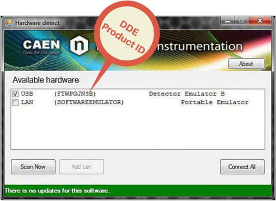
The code between the brackets to the right of “USB” is the DDE Product ID
EASY (Embedded Assembly SYstem) is the CAEN high/low voltage power supply to be used every time the magnetic field and radiation become a problem.
For More information about EASY Products click here.
Why EASY?
During the last decade, CAEN has been involved in developing different solutions in order to satisfy the requirements coming from main LHC experiments where the electronic equipment of the experiment is dealing with high dose of radiation and strong magnetic field.
In order to provide safe and reliable operations in these hostile areas, CAEN started tests with rad-tolerance components and magnetic field resistant solutions, patenting this technology that is now used in a line of products for “hostile” area.
In addition even if designed for harsh environment the EASY modules can work also in normal conditions with excellent performance.
Widely used in LHC experiments, producing over 6,500 electronic units, containing more than 190,000 sub-boards.
In addition even if designed for harsh environment the EASY modules can work also in normal condition with excellent performance.
System Philosophy
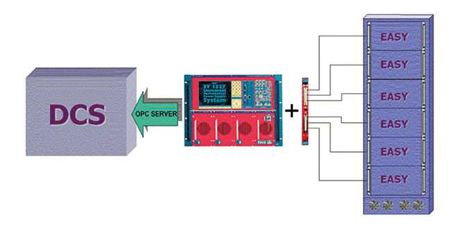
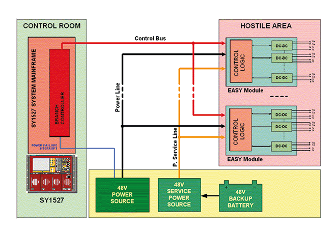
The power supply is located directly in the hostile area; here the EASY modules provide a wide variety of output voltages to satisfy the requirements of most detectors and front end electronics (LV up to 100A and HV up to 12 kV).The control of the EASY power supply system can be done remotely using a Branch Controller (model A1676A) plugged in a SY1527 or SY2527 mainframe located in the control room. Trough the mainframe an immediate and “automatic” interfacing with the DCS or the custom control software is achieved using the provided and full reliable OPC server software.
Flexibility and Compatibility
Each branch controller module can handle up to 6 EASY crates. Since the A1676A is a one unit wide board, each SY1527 power system can house up to 16 branch controller boards, while each SY2527 can house up to 6 branch controller boards, enabling the monitoring up to 96 EASY systems. The module can work even side by side with standard HV and/or LV board. An unique interface and a cost effective set-up for all the experiment’s power requirements!
Architecture
The EASY3000 (for boards up to 40cm long, A3XXX Family) can house up to 10 boards depending on the boards’ width, while the EASY4000 (for boards up to 55cm long, A4XXX Family) can house up to 9 boards. As illustrated in Figure, the branch controller is the interface between the supply unit (SY1527 or SY2527) and the remote boards in the EASY crate. The branch controller role is to configure the EASY channels as they belong to the supply unit slot in which the branch controller is located. In this way all the channels of the EASY boards, will be considered as channels of the branch control board, increasing hugely the number of channels the system can handle.
EASY3000/4000 Crates and Boards hostile areas tolerances
- Magnetic field: 2 kGauss
- Radiation:
- 1·1011 p/cm2 TD
- 2·1012 n/cm2 TD
- 15 kRad TID
CAEN offers its new modular High Voltage Power Supply System in a unique pack including all the options available at an attractive price.
The Premium Version is available as an ordering option of the SY4527 and SY5527 products. The Premium Version features:
- 10,4″ LCD Touch Screen (5.7″ for SY 5527)
- Full Version of the CPU
- Advanced Control Software
- Wi-Fi capability for remote wireless control
LCD
The wide LCD touch screen allows the user to easily take advantage of the brand new Control software developed by CAEN.
Advanced Software
The new SY4527 beneficial of a completely redesigned control software:
This new software is embedded in the system and can be installed on a PC, Laptop or Tablet too for local and remote control. It is Windows and Linux compatible (only Windows for Tablets) an it is possible to control up to 4 systems and to set and monitor the parameters of all the High Voltage Boards. The visualization of the different boards and their parameters is completely customizable and groups can be created for common settings. It is also possible to save settings in a mass storage device and restore them later if necessary.
In addition the advanced version of the software introduces Logging and Scripting Capability. The Logger is a useful tool which records every command sent to the system and every warning/alarm detected by the system. In this way it is possible to automatically monitor the behaviour of every single parameter during operations. Complex and advanced commands can be managed through the Scripting capability. Based on a simple proprietary syntax, this tool ensures flexible and fully customizable control on every system and board aspect.
Wi-Fi
The WiFi Dongle makes possible the wireless remote control.
CPU
The FULL CPU Version provides the complete set of panel connectors, the ENABLE, RESET, INTERLOCK control sections, and front panel fan speed control.
The A3818 windows driver is not certified by Microsoft®. The driver can still be installed on Windows PCs by disabling the system service for the driver signature check (i.e. Secure Boot Function in UEFI firmware interface of recent computers).
The Secure Boot function (i.e. the execution of signed modules) is only present on PCs with UEFI, the firmware interface that replaces the BIOS of the old PCs. The secure boot is activated / deactivated on Windows 10 systems with UEFI with the following commands:
Recovery > Restart now (menu Advanced Startup) > Troubleshoot > Advanced options> UEFI firmware settings > SecureBoot ON/OFF in “Security” UEFI menu
On a Lenovo laptop PC, showing driver installation problems due to signatures, the system information is as follows:
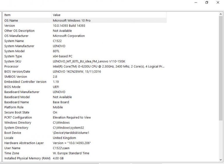
In particular:
- BIOS mode = UEFI
- Secure Boot state = ON
With this configuration, the driver signature problems (CAENUSB dated 19/12/17 and A3818 2.0 currently available on the CAEN website) can be found. By disabling secure boot, drivers can still be installed.
On PCs with the classic BIOS (legacy) the Secure Boot is not supported and, although on Win10 there is still the option to activate / deactivate it, this has no effect. This is made even more evident by the absence of the “UEFI firmware settings” menu on systems with legacy BIOS.
Typical system information of a PC with Legacy BIOS are the following:
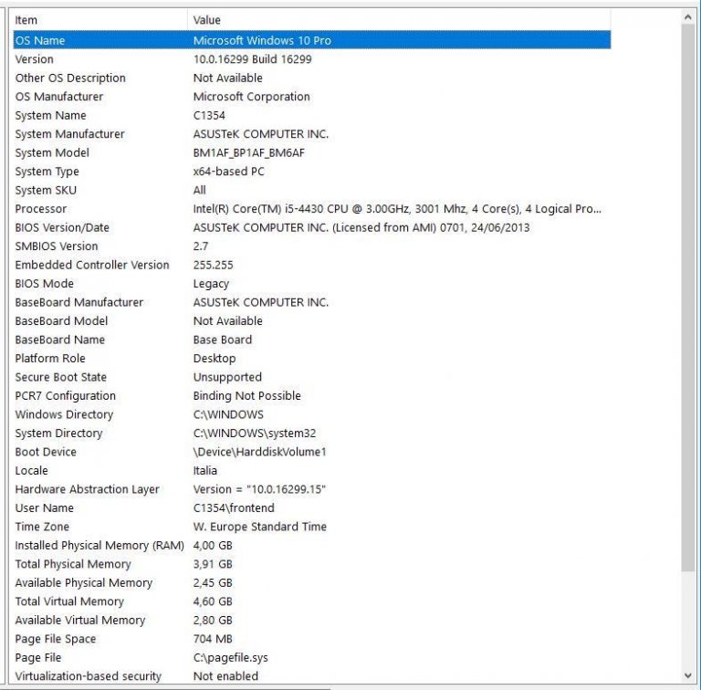
In particular:
- Windows 10 with updates up to December 2017
- BIOS mode = legacy
- Secure Boot state = unsupported
With this configuration, the driver signature problems are not found (CAENUSB and A3818 installed correctly and working). Of course, disabling or enabling secure boot has no effect because of the legacy BIOS.
In general, you can choose to load the operating system via UEFI or BIOS legacy mode when installing Windows. It could also work using a special tool to switch from BIOS to UEFI. All explained here: https://docs.microsoft.com/en-us/windows-hardware/manufacture/desktop/boot-to-uefi-mode-or-legacy-bios-mode
The A3818 is PCI Express v2.0 fully compliant card. CAEN cannot guarantee compatibility with PCI Express v3.0 (or higher) out of the tested solutions even if backward compatibility is declared by the computer manufacturer.
CAEN A3818 has been tested on the following list of computer solutions available on the market:
- Entry-level Solution (Windows 10 Pro – Linux)
- 1. Shuttle XH110G
- Middle-level Solutions (Windows 10 Pro – Linux)
- 1. ASUS ESC500 G4 Workstation
- 2. FUJITSU Workstation CELSIUS W570 power+
- High-level Solutions (Linux)
- 1. GOMA SERVER S_GAP-151R_Broadwell-EP-1
- 2. HP DL380 gen10 Server
- 3. HP ProLiant DL120 G7 Server
Contact CAEN for any further information.
CAEN Power Supply units can be distinguished according to their
connection to electrical ground. We provide three main boards
architectures:
- Common Ground
- Common Floating Return
- Individual Floating Channel
Common Ground
The Common Ground configuration is somehow the simplest.
Power supplies of this kind have the channel voltage reference hardwired to the chassis/crate ground.
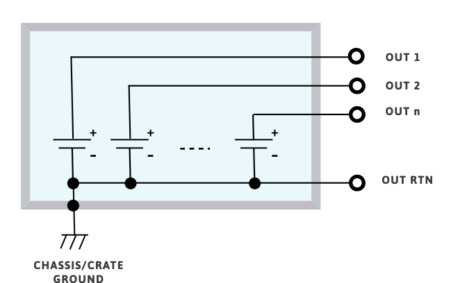
Common Floating Return
The Common Floating Return boards have channels sharing onecommon ground, which is insulated from the chassis/crate ground.
This feature may help to minimize
problems of ground-loops. The level of insulation from the channel return to chassis/crate ground may vary between different types of boards.
Generally the common floating return is insulated from chassis /crate ground up to few tens of volts.
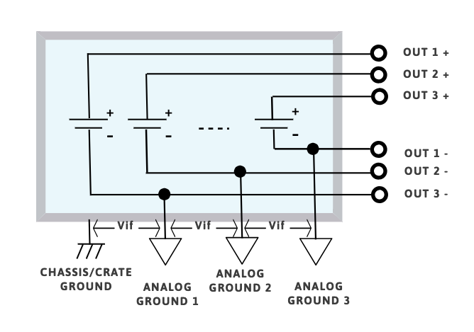
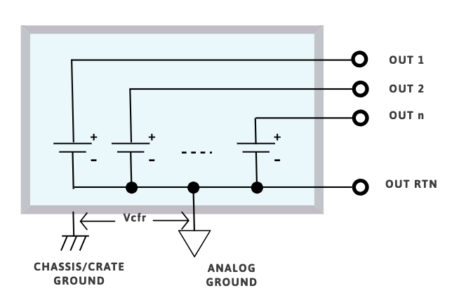
Individual Floating Channel
The Individual Floating Channel boards have independent channel returns insulated from chassis/crate ground from few tens of volts up to 5 kV.
In this configuration each channel can be connected to a different ground. If the maximum floating voltage is higher than the maximum channel voltage the channel is defined as FULL FLOATING.
A FULL FLOATING channel behave exactly like a battery; by grounding the + terminal it’s possible to get a negative voltage and by grounding the – terminal it’s possible to get a positive voltage (and it is also possible to mix positive and negative polarity outputs).
CAEN VME Digitizers are compatible with all CAEN VME & VME64X crates. However, CAEN VME64x Digitizers are only compatible with CAEN VME64X crates due to mechanical match requirements.
CAUTION: do not use the CAEN V/VX1740, V/VX1751, V/VX1730, V/VX1743, V/VX2740, V/VX2745, and VX2730 digitizers with VME8001, VME8002, VME8004, and VME8004A crates: overheat may damage the modules.
The following table shows the compatibility of all CAEN VME CRATES with all digitizers.
| DIGITIZER | VME8004X | VME8008X | VME81001 (VME64x) | VME8200 | μ-crate | NV8020A | VME8004B | VME8008B | VME8010 | VME8011 | VME8100 (VME)2 | VME8001 | VME80023 | VME80043 | VME8004A3 |
|---|---|---|---|---|---|---|---|---|---|---|---|---|---|---|---|
| VX2730 | ✓ | ✓ | ✓ | ✓ | ✓ | ||||||||||
| V2740 | ✓ | ✓ | ✓ | ✓ | ✓ | ✓ | ✓ | ✓ | ✓ | ✓ | ✓ | ||||
| VX2740 | ✓ | ✓ | ✓ | ✓ | ✓ | ||||||||||
| V2745 | ✓ | ✓ | ✓ | ✓ | ✓ | ✓ | ✓ | ✓ | ✓ | ✓ | ✓ | ||||
| VX2745 | ✓ | ✓ | ✓ | ✓ | ✓ | ||||||||||
| V1720 | ✓ | ✓ | ✓ | ✓ | ✓ | ✓ | ✓ | ✓ | ✓ | ✓ | ✓ | ✓ | ✓ | ✓ | ✓ |
| VX1720 | ✓ | ✓ | ✓ | ✓ | ✓ | ||||||||||
| V1724 | ✓ | ✓ | ✓ | ✓ | ✓ | ✓ | ✓ | ✓ | ✓ | ✓ | ✓ | ✓ | ✓ | ✓ | ✓ |
| VX1724 | ✓ | ✓ | ✓ | ✓ | ✓ | ||||||||||
| V1725s | ✓ | ✓ | ✓ | ✓ | ✓ | ✓ | ✓ | ✓ | ✓ | ✓ | ✓ | ✓ | ✓ | ✓ | ✓ |
| VX1725S | ✓ | ✓ | ✓ | ✓ | ✓ | ||||||||||
| V1730S | ✓ | ✓ | ✓ | ✓ | ✓ | ✓ | ✓ | ✓ | ✓ | ✓ | ✓ | ||||
| VX1730S | ✓ | ✓ | ✓ | ✓ | ✓ | ||||||||||
| V1740 | ✓ | ✓ | ✓ | ✓ | ✓ | ✓ | ✓ | ✓ | ✓ | ✓ | ✓ | ||||
| VX1740S | ✓ | ✓ | ✓ | ✓ | ✓ | ||||||||||
| V1742 | ✓ | ✓ | ✓ | ✓ | ✓ | ✓ | ✓ | ✓ | ✓ | ✓ | ✓ | ✓ | ✓ | ✓ | ✓ |
| VX1742 | ✓ | ✓ | ✓ | ✓ | ✓ | ||||||||||
| V1743 | ✓ | ✓ | ✓ | ✓ | ✓ | ✓ | ✓ | ✓ | ✓ | ✓ | ✓ | ||||
| VX1743 | ✓ | ✓ | ✓ | ✓ | ✓ | ||||||||||
| V1751 | ✓ | ✓ | ✓ | ✓ | ✓ | ✓ | ✓ | ✓ | ✓ | ✓ | ✓ | ||||
| VX1751 | ✓ | ✓ | ✓ | ✓ | ✓ | ||||||||||
| V1761 | ✓ | ✓ | ✓ | ✓ | ✓ | ✓ | ✓ | ✓ | ✓ | ✓ | ✓ | ✓ | ✓ | ✓ | ✓ |
| VX1761 | ✓ | ✓ | ✓ | ✓ | ✓ |
1 Obsolete models.
2 Models of the VME8100 series equipped with VME64X backplane.
3 Models of the VME8100 series equipped the VME64 backplane.
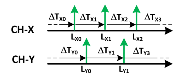
The A5203 and DT5203 supports Common Start, Common Stop, Trigger Matching and Streaming acquisition modes as described in the following lines.
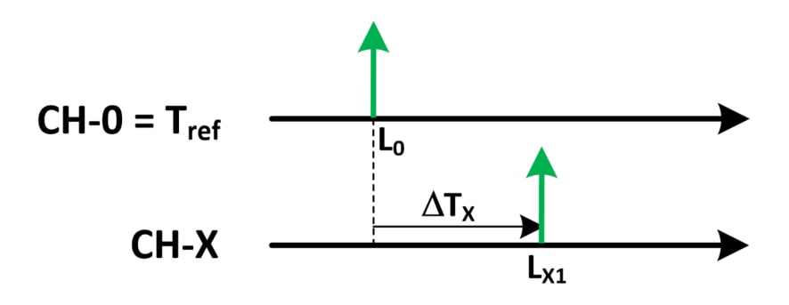
Common Start
Ch O is the common start that opens the acquisition gate and represents the time reference for the acquisition. All the other N channels provide DT time measurements with respect to the reference channel. The gate width is programmable by software. Any hit falling outside the gate will be discarded. In the case of multiple hits fall inside an acquisition window for the same channel, only the first will be used for the DT (although all multiple hits will be acquired by the picoTDC).
The event data are composed by:
- Trigger ID
- 56 bit coarse time stamp (LSB = 12.8 ns) for the absolute time
- List of To for all the channels: the Tref (i.e. Ch 0) fine time stamp (minimum LSB = 3.125 ps) and the list of DT (minimum LSB = 3.125 ps) for the channels from 1 to 63 (only those channels that have been hit)
- List of ToT (if enabled)
It is possible to save the leading edge only, or leading edge + ToT of the recorded hits.
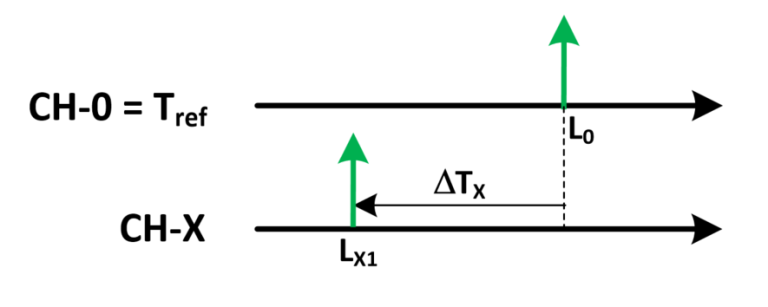
Common Stop
Similar to common start, but the common time reference on Ch 0 is used as a stop that closes the acquisition gate. In case of multiple hits only the last one before the stop will be used.
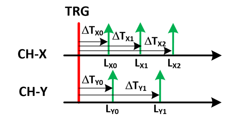
Trigger Matching
A trigger signal (typically coming from the LEMO 00 inputs) defines a data acquisition window with programmable width and offset. All hits falling within that window will be recorded. Multi-hit acquisition is supported. All time measurements are referred to the start of the acquisition window with coarse timing resolution (LSB = 25.6 ns). However, the relative timing between the channels keeps the maximum resolution of 3.125 ps.
The event data are composed by:
- Trigger ID
- 56 bit coarse time stamp (LSB = 12.8 ns) for the absolute time of the trigger
- List of the hit time stamps (ToA) of all channels (minimum LSB = 3.125 ps)
- List of ToT (if enabled)
It is possible to save the leading edge only, leading edge and trailing edge, or leading edge + ToT of the recorded hits.
Streaming
This acquisition mode implements a continuous hit recording, without any gate or trigger windowing. All hits received by the inputs are converted into a 64 bit time stamp (minimum LSB = 3.125 ps) and saved in the form of a sorted list. It is possible to save leading edge only, leading edge plus trailing edge or leading edge plus ToT (coming soon)