
8 Ch Dual Range Multievent Peak Sensing ADC
V1785
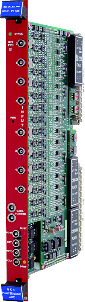
The Mod. V1785 is a 1-unit wide VME 6U module housing 8 Peak Sensing Analog-to-Digital Conversion channels. Each channel is able to detect and convert the peak value of the positive analog signals (with >50 ns risetime) fed to the relevant connectors. Input voltage range is 0 ÷ 4 V. Each channel is processed by two gain stage (x1 and x8) in parallel followed by the ADC stage: a dual input range is then featured: 0 ÷ 4 V (1 mV LSB) and 0 ÷ 500 mV (125 μV LSB); this allows to avoid saturation with big input signals while increasing resolution with small ones.
The ADCs use a sliding scale technique in order to reduce the differential non-linearity.
Programmable zero suppression, multievent buffer memory, trigger counter and test features complete the flexibility of the unit.
The module works in A24/A32 mode. The data transfer occurs in D16, D32, BLT32 or MBLT64 mode. The unit supports also the Chained Block Transfer (CBLT32/CBLT64) and the Multicast commands.
The VME interface is VME64 and VME64X standard compliant and features the A24/A32 and MultiCast addressing modes. The data readout occurs either in D32, BLT32, MBLT64 mode, or in daisy chain with 32/64 bit Chained Block Transfers. The module features a fully programmable RORA interrupter.
The board is provided with the P1 and P2 VME connectors and fits into both V430 and standard 6U crates. It also supports the “live insertion”, allowing the User to insert (or remove) the board into (or from) the crate without switching it off.
Features
-
Two simultaneous ranges: 0 ÷ 4 V / 0 ÷ 500 mV
-
12 bit resolution with 15 bit dynamics
-
125 µV LSB on low range, 1mV LSB on high range
-
2.8 µs / 8 ch conversion time
-
600 ns fast clear time
-
Zero and overflow suppression for each channel
-
±0.1 % Integral non linearity
-
±1.5 % Differential non linearity
-
32 event buffer memory
-
BLT32/MBLT64/CBLT32/CBLT64 data transfer
-
Multicast commands
-
Live insertion
V1785: Manuals

V1785: Download
Applications SW
Request a Quote

Footer

