
12 Channel 3 kV, 10/200 µA Board
A1821H
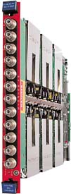
The Model A1821 board house 12 HV channels with either positive (A 1821HP) or negative (A 1821HN) polarity. The Mod. A 1821 output channels offer either 3 kV / 200 µA or 3 kV / 10 µA full scale range (dip-switch selectable); Two special versions with different channel configuration (A1821HM and A1821HMP are also available).
If the output voltage differs from the programmed value by more than 3% of voltage full scale range, the channel is signalled to be either in OVERVOLTAGE or UNDERVOLTAGE condition. Moreover, for each channel, a voltage protection limit SVMAX can be fixed via software with 1 V resolution and the output voltage can not be programmed beyond this value.
The HV RAMP-UP and RAMP-DOWN rates may be selected independently for each channel in the range 1÷ 500 V/s in 1 V/s steps.
The output current is monitored with 1 nA / 20 nA resolution depending on current range; if a channel tries to draw a current larger than its programmed limit it is signalled to be in OVERCURRENT condition; the SY1527 system detects this state as a fault and reacts according to the setting of the TRIP parameter, namely:
1) TRIP=infinite ( = 1000 s)
When the set output current value is reached the channel behaves like a constant current generator.
2) TRIP=finite (< 1000 s)
The output current keeps the set value only for programmed time interval and then is switched off.
The TRIP time (i.e. the maximum time an OVERCURRENT condition is allowed to last) can be programmed in 0.1 s steps.
The maximum output voltage (VMAX Hardware) can be fixed, through a potentiometer located on the front panel, at the same common value for all the board channels and this value can be read out via software.
The boards are provided with an “HV EN” input that disables the channels when it is not connected to ground
Features
- 12 channel HV board
- 0÷3 kV output voltage
- Dual range current (10 µA / 200 µA)
- Available with positive or negative polarity
- 250 mV Voltage Set / Monitor Resolution
- 1 nA / 20 nA Current Set / Monitor Resolution
- Voltage ripple smaller than 30 mV peak-to-peak
- Programmable TRIP parameter
- 1÷500 Volt/sec programmable Ramp Up/Down
- Current generator operation in Overcurrent condition
A1821H: Manuals

Request a Quote

Footer

