

Lorem ipsum dolor sit amet, no vidit nullam reprehendunt sit. Ex vix semper qualisque, te soluta efficiendi qui, corpora prodesset delicatissimi at nec. Sanctus convenire cu cum, pro deleniti platonem no. Est ex quem vulputate, vim accusata intellegam ea, sit an corrumpit deterruisset.
In ludus insolens usu. Ius quidam assentior omittantur id. Eos antiopam postulant ex, postea accusamus est cu. An eam vocibus assueverit, mea affert similique ex. Sit nihil tation ea, vix etiam ludus vocent an.
a
A
ADC Conversion Time
The time required, after the sample command, to digitize the analog signal
ADC Dead Time
The minimum amount of time required after the end of a GATE to have the ADC ready for a new acquisition
ADC Resolution
The number of bits in which the ADC full scale range is divided
Address Modifier
It is the code which carries the information about the size and the type of VME data transfer
Analog Adder
A linear Fan-In
AND
Logical designation or circuit function meaning that all inputs must be in the TRUE state for a TRUE output
Anti-Coincidence
An input signal which suppresses the normal functioning of the unit for the duration of its application
b
B
Backplane
A monolitic, multilayer printed circuit board at the rear of a crate providing bus dataway, power lines and modules’ connectors
Bandwidth
The frequency range over which the gain of an amplifier or other circuit does not vary by more than 3 dB
Baseline Restorer
A circuit that maintains the amplifier DC output (baseline) at fixed potential independently from counting rate
Baseline Shift
Drift of the amplifier DC level (baseline) that may impair the peak amplitude stability
Block Transfer (BLT32)
A 32 bit VME data transfer from/to a series of adjacent locations of a module
Bridged Outputs
Parallel output connections which share the same driver
c
C
CAMAC
Computer Automated Measurement And Control; international standard of modular instrumentation defined by the ESONE Committee of the JNRC (document EUR4100e, 1969 and subsequent revisions); CAMAC One single-width unit, as per IEEE Standard 583, has 305 mm x 182.9 mm x 17 mm overall dimensions.
They can, however, also be built in multiples of this standard, that is, double-width, triple-width etc.
CANbus
Controlled Area Network; network consisting of multiple microcontrollers that need to communicate with each other
Chained Block Transfer CBLT
Sequential read out of multiple VME slave modules selected by a single address cycle
Charge ADC
An ADC which measures the input charge integrated during the GATE period
Charge Sensitive Preamplifier
A preamplifier whose peak output amplitude is directly proportional to the input integrated charge
Coincidence Unit
A device which performs the AND logic function of two or more inputs
Common Mode Range
The maximum range (usually voltage) within which differential inputs can operate without a loss of accuracy
Common Mode Rejection Ratio
The ratio between the common mode input noise and the output voltage, expressed in dB. It expresses the ability to reject the common mode noise
Common Mode Noise
The noise which appears equally, and in phase, on the IN+ and IN- nodes of a differential input with respect to ground
Common Start
A signal common to all input ch. which marks the beginning of a time interval measurement in a TDC
Common Stop
A signal common to all input ch. which marks the end of a time interval measurement in a TDC
Complementary Output
A logical signal with its FALSE state and TRUE state reversed from that of the normal output signal
Constant Fraction Discriminator
A discriminator which allows to minimize time walk errors encountered triggering constant rise time and varying amplitude signals
Control and Status Register (CSR Space)
A register used to control the operation of a device and/or record the status of an operation. Its allocation and usage is part of the VME specification
Crosstalk
Unwanted coupling of a signal from one channel to another one
d
D
Daisy Chain
Connection of control signals on several boards in a chain
DC Level Shift
A programmable DC Offset
Differential Input
A circuit that is sensitive to the algebraic difference between the IN+ and IN- input signals
Differential Non-Linearity
The maximum deviation of the ADC bin widths from a flat distribution (expressed as %)
Differential Output
A circuit with two outputs that have equal but opposite signal excursions around a fixed potential (called the common mode level)
Double Pulse Resolution (DPR)
The minimum pulse pair resolving time (measured between leading edges of the incoming pulses)
Dual Port Memory
A memory module which has two interfaces through which data can be transferred
Dwell Time
The trigger generation period of the internal programmable timer of a MultiChannel Scaler
e
E
ECL
Emitter-coupled logic, an unsatured logic performed by emitter-coupled transistor. Normal ECL LOGICAL 0 = LOW = -1.75 V and LOGICAL 1 = HIGH = -0.9 V
Event Counter
A counter which indicates the number of trigger signals that a DAQ module has processed
f
F
Fall time
The time required for a pulse to decrease from 90% to 10% of full amplitude.
Fan-In
The mixing of more than one input to obtain one of the following outputs:
Linear > the algebraic sum of the inputs
Logic > the logical OR of the inputs
Fan-Out
The reproduction of an input signal on more than one output
FWHM
Full Width at Half Maximum, the width of a pulse or waveform at 50% amplitude
g
G
GATE
An input control signal used to enable the passage of other signals
Geographical Addressing
Addressing of a module according to its physical location (the slot number) in a crate
Ground Loop
A low impedance path along which voltage drops occur due to external pick-up
h
H
High Speed CAENET
A CAEN proprietary 1 Megabit/second serial transmission protocol
i
I
Inhibit
A signal or switch which prevents a unit from operating or responding to inputs
Integral Non-Linearity
Maximum deviation (expressed as fraction of full scale) of ADC response from a straight line fit
Interchannel Isolation
Cross talk rejection ability
I/O Register
A device capable of either receiving or sending a pattern of logical signals
j
J
JAUX
In a VME V430 compliant backplane, a 3 row, 30 pin connector (jack) providing “2 V, -5 V” (useful to supply ECL electronics without the need of on-board DC-DC converters) and ±15 V power lines, geographical address lines (SN1-5) and some User defined lines (CK, SG, CL)
l
L
Latch
Memory register
Latching Scaler
A scaler where the counters can be latched “on the fly” without interfering on data acquisition process
Leading Edge Discriminator
A device that delivers, for each input signal that is larger than a programmable threshold, a logic pulse
Live Insertion
The possibility of inserting (or removing) a board into the crate without switching it off
Low Threshold Discriminator
A Leading Edge Discriminator with high sensitivity on small signals
LSB
Least Significant Bit
LVDS
Low Voltage Differential Signaling (specified in the IEEE 1596.3 standard), it’s a way to communicate data using a very low voltage swing (about 350 mV) over balanced connections
m
M
Majority Logic
Generates a TRUE output when the number of coincident inputs is equal to or greater than some specified threshold
Master
A device which is capable of controlling the data transfer operation according to some protocol
MBLT64
Multiplexed BLT; it is a data cycle similar to the BLT, but it transfers 64 bit words instead of 32 bit ones
Multicast Mode MCST
Multicast (MCST) Mode allows commands to be sent to chosen set of VME slave modules in only one data transfer bus transaction
Multichannel Scaler
A scaler provided with a number of independent channels and a periodical programmable trigger, that allows to record counting rate as a function of time
Multievent Buffer
A FIFO-like buffer where it is possible store/read the data belonging to multiple triggers
Multihit TDC
A TDC that can accept multiple hits per channel
n
N
NAND
A complementary output AND circuit
NIM
Nuclear Instrumentation Module, international standard of modular instrumentation defined by U.S. NIM Committee (AEC Report TID-20893); NIM modules must have a minimum standard width of 1.35 inches (3.43 cm), a height of 8.75 inches (22.225 cm) and a 10 inches depth (25.4cm). They can, however, also be built in multiples of this standard, that is, double-width, triple-width etc
NIM Logic Levels
Inputs:
- LOGICAL 1 = -12 to 32 mA, or 600 mV to 1.6 V into 50 Ohm
- LOGICAL 0 = < +2 mA or <100 mV into 50 Ohm
Outputs:
- LOGICAL 1 = -14 to 32 mA, or 700 mV to 1.6 V into 50 Ohm
- LOGICAL 0 = < +2 mA or <100 mV into 50 Ohm
Non-updating Discriminator
A discriminator whose output must return to a zero, or “off”, state before retriggering can occur.
NOR
A complementary output OR circuit
o
O
- OR
A logic circuit having the property that if at least one input is TRUE the output is TRUE - Overflow Suppression
A digital technique which allows to skip from the memory “out of range” values
p
P
- PAUX
In VME V430 compliant boards, a 3 row, 30 pin connector (plug) that mates with the JAUX connector - Peak Sensing ADC
An analog to digital converter which measures the peak amplitude of waveforms occurring within the GATE period - Pedestal
The ADC value readout when no input signal is present - Pile-up
The overlapping of amplifier output signals due to excessive count rate - Pole Zero Cancellation
A circuit that eliminates the undershoot of semi-gaussian shaped output pulses - Power Supply Rejection
The ability of a device to reject the effects of power supply variations - Programmable Logic Unit
A module which accepts a number of inputs and generates a logic combination of the inputs according to programmed operations
q
Q
QDC
Charge ADC
r
R
Reflection Coefficient
The amount of signal amplitude that is reflected by an input due to impedance mismatchRise Time
The time required for a pulse to grow from 10% to 90% of full amplitudeRMS
It is the square root of < (X-< X >)2 > where X is a random variable and < > denotes the average
s
S
Sample and Hold
A circuit that on command samples and holds the instantaneous amplitude of an input signal
Sampling ADC
A device which samples an input waveform at specified time intervals, digitizes the analog values at the sampled points and stores the results in a digital memory
Scaler
Counter
Semi-gaussian shaping
The pulse shape which resembles to a Gaussian curve obtained by CR-(RC)n filters with equal time constants
Shaping amplifier
An amplifier that accepts the output pulses from a charge-sensitive pre-amplifier and shapes them in order to improve the S/N ratio and minimise the risk of pile-up (tipically in energy spectroscopy applications)
Shaping time
The time constant of a shaping amplifier filter
Single Ended Signal
Ground referenced signal
Sliding Scale Technique
A technique employed to reduce ADC differential non linearity
t
T
TAC
Time to Amplitude Converter
TDC
Time-to-Digital Converter
Translator
A device which changes logical signals from one standard to another (e.g. from TTL to ECL)
TTL
Transistor-Transistor-Logic.
Logical 0: 0 to 0.8 V;
Logical 1: 2.0 to 5.0 V
u
U
Updating Discriminator
A discriminator that can be retriggered before the output returns to zero
v
V
V430
It is a VMEbus compatible crate type; in addition to the standard 3 row , 96 pin J1/J2 VME connectors, the V430 backplane adopts an extra JAUX connector providing ?2 V, -5 V (useful to supply ECL electronics without the need of on-board DC-DC converters) and ±15 V power lines, geographical address lines (SN1?5) and some User defined lines (CK, SG, CL)
Veto
Inhibit
VME
Versa Module Eurocard; Master/Slave modular asynchronous computer architecture, used for data transfer, storage and processing (defined by IEEE-1014-1987 specifications); three card heights are allowed with VME; 3U, 6U, or 9U (1U = 43.60mm); a single slot card is 6T wide (1T = 5.08mm ). Length is either 160mm or 340mm.
VME64
An extension of the original VME specifications as defined by ANSI/VITA 1-1994; it offers, among the other features, larger 64-bit data path and 64-bit addressing range
VME64x
A further extension of VME64 standard, providing, among the other features, geographical addressing capability and larger bandwidths for data transfer
VME64xP
VME64x extension for Physics: it features characteristics, stated as options in VME64x, helpful for the typical requirements of physics experiments, such as further user defined I/O pins and sparse data readout capability
VSWR
Voltage Standing Wave Ratio: VSWR=Ei+Er/Ei-Er, where Ei is the incident wave amplitude and Er the reflected one
z
Z
Zero Suppression
A digital technique that allows to skip from the memory the values that lie below a programmable threshold
m
M
Maximum Output Current
The maximum value of the current drawn by a channel
p
P
Polarity
The sign of the output voltage with respect to the ground reference (positive, negative or floating)
Power Supply Units Grounding
CAEN Power Supply units, can be distinguished according to their connection to electrical ground. We provide three main boards architectures
Common Ground
Power supplies of this kind have the channel voltage reference hardwired to the chassis/crate ground
Common Floating Return
The Common Floating Return boards have channels sharing one common ground, which is insulated from the chassis/crate ground. This feature may help to minimize problems of ground-loops. The level of insulation from the channel return to chassis/crate ground may vary between different typologies of boards. Generally the common floating return is insulated from chassis /crate ground up to few tens of volts.
Individual Floating Channel
The Individual Floating Channel boards have independent channel returns insulated from chassis/crate ground from few tens up to 500 V. In this configuration each channel behave exactly like a battery: by grounding the + terminal, it’s possible to get a negative voltage and by grounding the – terminal, it’s possible to get a positive voltage (and it is also possible to mix positive and negative polarity outputs).
r
R
Ramp Up/Down
The output voltage slew rate at turning ON/OFF
Ripple
The amount of AC voltage that is superimposed on the DC output voltage (measured pp at full load from DC to 15 MHz)
s
S
SCADA
Supervisory Control And Data Acquisition; it is a purely software package that is positioned on top of hardware to which it is interfaced, in general via Programmable Logic Controllers, or other commercial hardware modules. It is not a full control system, but rather focuses on the supervisory level
t
T
Trip Time
The maximum time an overcurrent condition is allowed to last
v
V
VMAX hardware
The hardware upper limit of the output voltage, set as a safety threshold
VMAX hardware accuracy
The maximum departure between the set value and the actual value of VMAX hardware (expressed as % of FSR)
VMAX software
The maximum programmable value of the output voltage (in any case the output voltage is not allowed to exceed the VMAX limit)
VMAX software resolution
The minimum step for VMAX software programming
Voltage Monitor vs. Output Voltage Accuracy
The maximum departure of the VMON value from the actual VOUT value (expressed as % of reading + offset, from 10% to 90% of FSR)
Voltage Set vs. Voltage Monitor Accuracy
The maximum departure of the VSET value from the VMON value (expressed as % of setting + offset, from 10% to 90% of FSR)
Voltage Monitor Resolution
The minimum step for the output voltage monitoring
Voltage Set Resolution
The minimum step for the output voltage programming
Power Supply
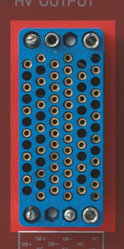
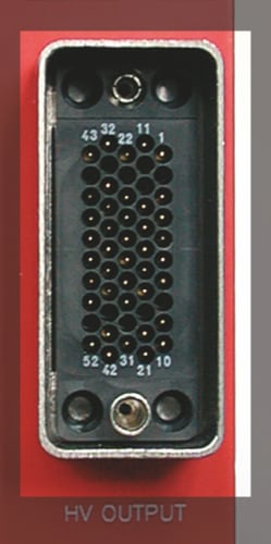
Factory Name: AMP 201311-3
Description: HV multipin connector
Other features: Mates with AMP 201310 cable connector; suitable for operation in the -55 ÷ +150 °C range
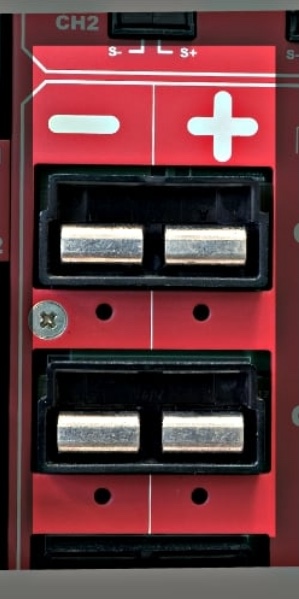
Factory Name: APP PC5933T
Description: Vertical contact MINI P/CLAW APP PC5933T type
Other features –
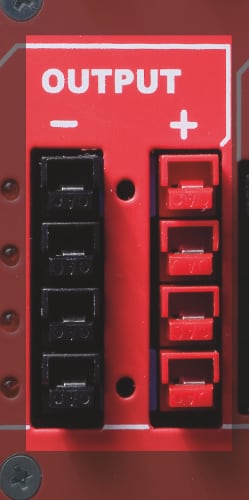
Factory Name: APP30 1317G4 / PP30 1327BK / PP30 1327G6BK
Description: APP30 1317G4 type
Other features: APP30 MOUNTING WINGS 1399G8BK type:
- Black: PP30 1327G6BK APP
- Red: PP30 1327BK APP
- Vert. contact PP30 1317G4 APP
- Mounting: PP30 MOUNTING WINGS 1399G8BK APP
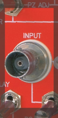
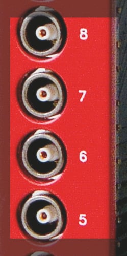
Factory Name: Radiall R141603
Description: BNC type coaxial connector
Other features –
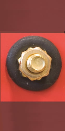
Factory Name: RS Stock no. 483-2390
Description: Brass hexagon head set screw, M6x30mm
Other features –
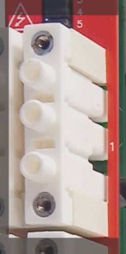
Factory Name: CPE 28-019
Description: HV 3 Pin Panel Male Connector
Other features: supports up to 18 kV
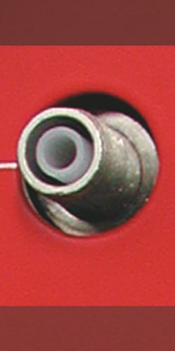
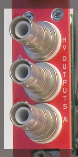
Factory Name: CPE 23.100.151.046
Description: HV Coaxial Connector
Other features: supports up to 18 kV; mates with HV Cable Connector CPE 23.100.052.045
Factory Name: DC8W8SA00LF
Description: Power Connector 8W8 Socket
Other features: mates with DC8W8PA00LF
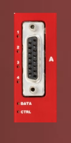
Factory Name: Amphenol FCI ICD26S13E4GV00LF
Description: Amphenol FCI 15 Pin D-Sub Female PCB Straight
Other features –
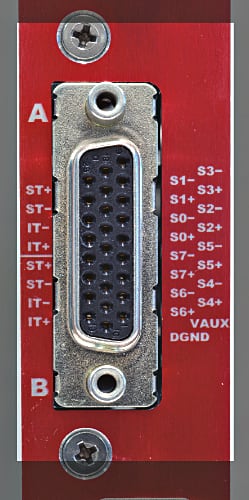
Factory Name: FCI ICD26S13E4GV00LF
Description: Connector High Density D-Sub SKT 26 POS 2.28mm Solder RA Thru-Hole 26 Terminal Port
Other features –
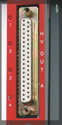
Factory Name: DB37
Description: FCI DCPV37S300GT
Other features –

Factory Name: KINGS 1064-1
Description: KINGS HV coaxial connector
Other features: Supports up to 15 kV
Factory Name: Fischer DP101A004-51
Description: LEMO type coaxial connector
Other features –

Factory Name: LEMO HV ERA3S415CTL
Description: LEMO HV Female (panel)
Other features: mates with LEMO HV MALE FFB3S415CPAC-10W
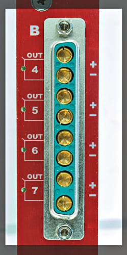
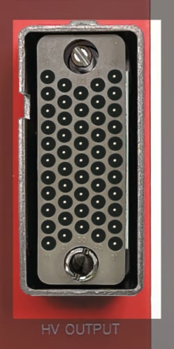
Factory Name: Radiall 691 803 004
Description: HV multipin connector
Other features: Mates with Radiall 691 802 002 and CAEN Mod. A996 cable connectors; up to 9 kV supported
Factory Name: SAG.H51.LLZBG
Description: HV Multipin Connector
Other features –
Factory Name: Radiall R317580
Description: HV coaxial connector
Other features: Supports up to 8 kV
Front-end
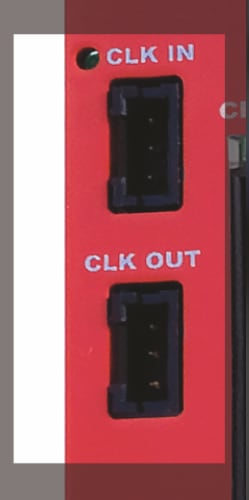
Factory Name: AMP 3-102203-4 (Series: AMPMODU)
Description: Connector header 3 pin 2.54 mm
Other features –
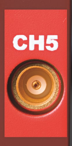
Factory Name: Radiall R141603
Description: BNC type coaxial connector
Other features –
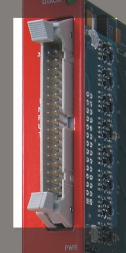
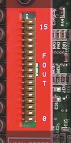
Factory Name: 3M 3431-6202 (17+17 pin); 3M 3408-5202 (8+8 16 pin)
Description: Header-type connector
Other features: Available with different pin sets; the 17+17 connector mates with 3M 3414-6600 wire mount connector
Factory Name: Fischer DP101A004-51
Description: LEMO type coaxial connector
Other features –
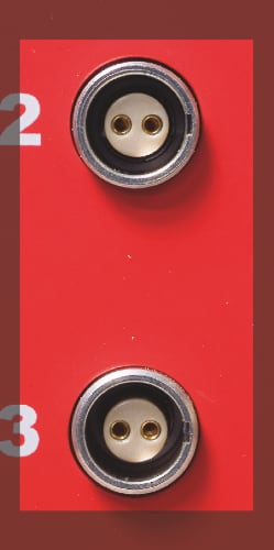
Factory Name: EPG.0B.302.HLN
Description: LEMO 2 pin type
Other features –
Factory Name: SUHNER CS 85MCX-50-0-16
Description: 50 Ω MCX connector
Other features –
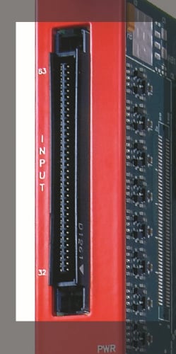
Factory Name: 3M P50E-068P1-SR1
Description: Robinson Nugent 68 pin straight angle thru-hole board mount connector
Other features: Mates with:
3M P25E-068S (SY2791)
3M P50E-068S (other modules)
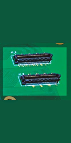
Factory Name: 0.40 mm Razor Beam™ LP Ultra Fine Pitch Socket Strip
Description: Samtec 28+ Gbps Solution, Ultra fine 0.40 mm pitch; 80 I/Os
Other features –
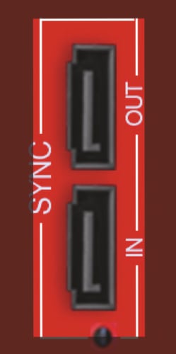
Factory Name: MOLEX 47080-4005
Description: 1.27 mm Pitch Serial ATA Shrouded Signal Plug
Other features –
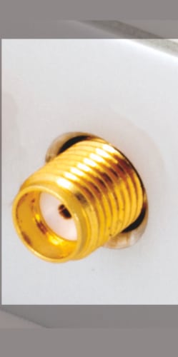
Factory Name: Johnson 142-0701-871
Description: SMA 50 Ohm connector
Other features –
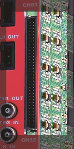
Factory Name: ERNI SMC-114805
Description: Dual Row 68 pin connectors
Other features –
Factory Name: AMP 5/826634/0 (17+17 pin)
Description: Male strip header (17+17 pin)
Other features: the 17+17 connector mates with 3M 3414-6600 wiremount connector
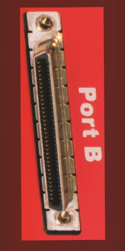
Factory Name: MOLEX 71430-0008
Description: 0.80mm Pitch VHDCI Receptacle, 68 Circuits
Other features –
Communication Ports
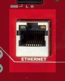
Factory Name: Ehternet
Description: ETH 10Base-T female connector TTL signals (TCP/IP)
Other features –
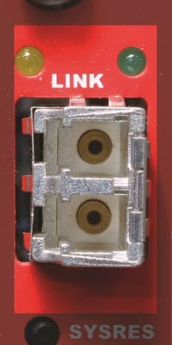
Factory Name: Agilent HFBR-5911L/AL
Description: LC type duplex connector
Other features –
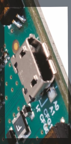
Factory Name: MOLEX 0473460001
Description: USB Micro type
Other features –

Factory Name: MOLEX SD-54819-026
Description: USB Mini type
Other features –
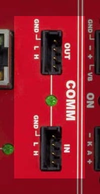
Factory Name: 280371-2
Description: Connector Header Through Hole 4 position 0.100″ (2.54mm)
Other features –
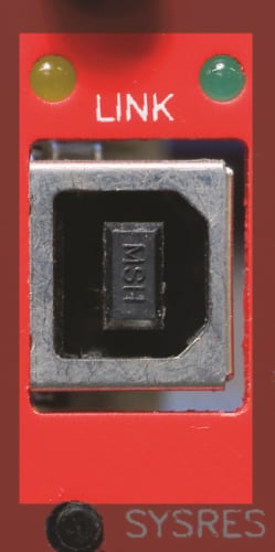
Factory Name: AMP 787780-2
Description: USB Type B
Other features –

